oldtuckunder Posted December 29, 2018 Author Share Posted December 29, 2018 49 minutes ago, JohnD said: Camshaft Part No Duration Intake Exhaust Lobe Centre Angle Lobe Lift Valve Lift RPM Notes Advertised I/E Open (BBDC) Close (ATDC) Open (BTDC) Close (ABDC) 1.46:1 1.55:1 OEM TR5/6, PI (UK) 307689 280 35 65 65 35 105 0.252 0.368 0.391 2000-6800 OEM TR5/6, 1969-1971 PI (UK) 256 18 58 58 18 110 0.240 0.350 0.372 Post 1971 Early TR6/GT6 Carb (USA) 240 10 50 50 10 110 0.220 0.321 0.341 Early TR6/GT6 Carb (USA) 256 18 58 58 18 110 0.240 0.350 0.372 2000-5000 Post 1972 308778 308778 270 25 65 65 25 0.230 0.336 0.357 1200-6800 OEM GT6 Mk2, Spitfire Mk2/3, 2.5PI early Cam(e) through fine, Alan! Love to have you actual degreeing file too! Hi John You shall have it! I just wanted to enter one more cam into it so that I can check that it will work in comparison mode before releasing it on the world! Interesting looking at the table you published, of course we now know that Duration, and Cam Timing numbers are meaningless without knowing at what cam lift height they were measured, and were they all measured at the same lift, also that the Valve Lift numbers are also incorrect as they don't correct for valve clearance and what the final full lift Rocker Ratio is. But nice set of authoritative looking numbers and we do know that at least the LCA is correct Alan Link to comment Share on other sites More sharing options...
122344 Posted December 29, 2018 Share Posted December 29, 2018 some cam specs. http://www.hottr6.com/triumph/tr6cams.html Link to comment Share on other sites More sharing options...
oldtuckunder Posted December 30, 2018 Author Share Posted December 30, 2018 On 12/29/2018 at 6:41 PM, 122344 said: some cam specs. http://www.hottr6.com/triumph/tr6cams.html Yes an interesting collection, but as the Author says without knowing where measurements were taken you have very little to confirm what you are comparing or even if the numbers are real. I see a few Cams had duration quoted at .050 which is useful. Alan Link to comment Share on other sites More sharing options...
oldtuckunder Posted December 30, 2018 Author Share Posted December 30, 2018 On 12/29/2018 at 5:04 PM, JohnD said: Love to have you actual degreeing file too! OK John just so you have something to do on New Years Eve, here is my final Sideways offering for 2018? Realised I didn't need to degree another real cam in order to test comparison, just add some for a fictitious lobe. Please find attached spreadsheet, with the data, some charts, and some instructions on how to drive. If anyone uses this to Degree a Cam please contribute it back to the thread, all you have to do is Copy and Paste the columns of data from your spread sheet into a Reply here, and anyone should be able to grab them and paste them into their own. Would be nice if we could build a reference of all the common Triumph profiles, my suspicion is that it would set a few Hares running! PS the Graphs work fine in Excel, but however I have spotted that in LibraOffice Calc that it can't quite keep labels, and lines in sync, although has a good stab at graphing the data. Early Happy New Year Alan CAM_Profiler.xls Link to comment Share on other sites More sharing options...
Nick Jones Posted December 30, 2018 Share Posted December 30, 2018 Thanks Alan. I want to try this but also to do a direct measured comparison of cam lift and valve lift. Have three engines with three different cams, but each with a challenge. One in the car and thus hard to measure without at least removing the rad to get accurate crank degrees, one out of the car and complete but cam not known (prob 15/58) and one on the engine stand with a 308778 (some lobes a bit down on lift) but without a head...... Have to build an engine for the GT6 though...... Link to comment Share on other sites More sharing options...
122344 Posted December 31, 2018 Share Posted December 31, 2018 While your in the shed here is a useful tool you could fab to occupy your time Link to comment Share on other sites More sharing options...
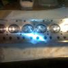
oldtuckunder Posted January 2, 2019 Author Share Posted January 2, 2019 Two people asked me how I set up the cam to measure it, and when I said on my ML7 lathe, they said "its not long enough" and whilst correct that the lathe bed isn't long enough to turn something as long as a 6cyl cam, it is (just) long enough to set it up to measure, so a couple of pictures to help. Alan With the Tail Stock right at the end, which whilst it doesn't look it is surprisingly firm. And the chuck removed, and a made up spigot that fitted in the old chuck spindle, the spigot locates in the centre of the cam, but is also wide enough to gently clamp the degree wheel. and voila it just fits with about an inch to spare. This was when I originally tried with the degree wheel the other end, but shows more clearly using the big speaker magnet to hold the base of the dial gauge firm but making it easy to move along the lathe bed. If I was doing it again I think I'd make a mount for the dial gauge that fitted on the cross bed so that I could just wind it up and down the bed. Link to comment Share on other sites More sharing options...
spitNL Posted January 3, 2019 Share Posted January 3, 2019 I usually don't post anymore, but nobody except, "gt6steve" and "122344" seem to have spotted the mistake made with measuring a cam without the lifter/tappet, and they haven't made any further replies, so here goes: You are measuring the cam lift with the tip of the dial gauge directly on the cam. This set up is only useful if you are are trying to replicate the grind. What you seem to be forgetting is that the point of contact between the tapper and camshaft doesn't stay in the center but moves closer to the edge during the opening and closing periods. The greater the acceleration of the tappet the more the point of contact moves to the edge. In fact the bigger diameter the tappet the more acceleration can be designed into the camshaft lobe. Difficult to say how much off your measurements are, but they won't be accurate. So you would have to also incorporate the tappet riding on the camshaft and measure from that, but getting it set up right will be difficult, because it would have to be in the same configuration as in the engine i.e. exactly perpendicular and with the same offset if there's any. IMHO putting the camshaft and tappet in the engine and measuring from that, like "122344" posted, will prove easier and more repeatable. Link to comment Share on other sites More sharing options...
JohnD Posted January 3, 2019 Share Posted January 3, 2019 9 hours ago, spitNL said: What you seem to be forgetting is that the point of contact between the tapper and camshaft doesn't stay in the center but moves closer to the edge during the opening and closing periods. The greater the acceleration of the tappet the more the point of contact moves to the edge. In fact the bigger diameter the tappet the more acceleration can be designed into the camshaft lobe. Please explain, it may be you and I are using different words. Do you mean this? I took the pic from Des Hamill's excellent "How to choose camshafts" (Veloce Press) John Link to comment Share on other sites More sharing options...
spitNL Posted January 3, 2019 Share Posted January 3, 2019 Yes, JohnD, thanks for posting the pic, that's what I meant. (the point of contact moves closer to the edge of the tappet) Something to keep in mind is that this happens not only close to full lift, but also on the rest of the opening and closing flanks. ps Surprised you like the book, I've got it myself and thought it wasn't very good, and although older, liking David Vizard's camshaft book much better. Link to comment Share on other sites More sharing options...
spitNL Posted January 3, 2019 Share Posted January 3, 2019 I think I have made a mistake in my previous posts in this thread; everywhere I say acceleration, should be velocity. Link to comment Share on other sites More sharing options...
Nick Jones Posted January 3, 2019 Share Posted January 3, 2019 Well spotted Frederick! You need to post more often...... Point is, it provides an angular offset as the camshaft centre is always the centre, but the point of contact isn't always on the centre-line of cam and follower....... Link to comment Share on other sites More sharing options...
oldtuckunder Posted January 3, 2019 Author Share Posted January 3, 2019 16 hours ago, spitNL said: I usually don't post anymore, but nobody except, "gt6steve" and "122344" seem to have spotted the mistake made with measuring a cam without the lifter/tappet, and they haven't made any further replies, so here goes: You are measuring the cam lift with the tip of the dial gauge directly on the cam. This set up is only useful if you are are trying to replicate the grind. What you seem to be forgetting is that the point of contact between the tapper and camshaft doesn't stay in the center but moves closer to the edge during the opening and closing periods. The greater the acceleration of the tappet the more the point of contact moves to the edge. In fact the bigger diameter the tappet the more acceleration can be designed into the camshaft lobe. Difficult to say how much off your measurements are, but they won't be accurate. So you would have to also incorporate the tappet riding on the camshaft and measure from that, but getting it set up right will be difficult, because it would have to be in the same configuration as in the engine i.e. exactly perpendicular and with the same offset if there's any. IMHO putting the camshaft and tappet in the engine and measuring from that, like "122344" posted, will prove easier and more repeatable. Interesting post thank you. I get your point that yes what I'm doing doesn't replicate the effect of the lobe wiping across the base of the follower (and your explanation has helped me understand something that had puzzled me in the past which was why wider followers were better. However, as I'm trying to compare cams that will be fitted in an identical block, with identical followers in identical offset/orientation to the cam lobes I'm not sure how much difference it would make, although a tiny glimmer of light is permeating my brain as I type this, in that I can now visualise that the profile of the flank prior to the tip could make a significant difference in the velocity of the follower towards the end of the lift phase, that wouldn't be apparent from how I am measuring the profile. i.e. if the profile allows the tip to come into contact with the follower towards its edge, then the cam rotation would wipe the tip across the follower lifting it faster than measuring the change in profile of the lobe would indicate. Interesting! Given that at about this time in the lift cycle if I read correctly, one of the objectives towards the tip is to try and slow the velocity of the follower/valve because we are about to make an abrupt change of direction and don't want the follower/valve still heading north at a great velocity whilst the lobe has started heading south and have the spring slam the follower back down on the lobe, I can see why the profile is so critical either side of the lobe tip. I wonder if this explains why in the couple I have measured so far (as I commented somewhere earlier in the thread) that I was surprised how short/shallow the tip duration was on both like max 1-2 deg cam rotation. But yes I now see why if you really wanted to compare the effective lift profile of two cams as opposed to the physically ground in lift profile, then yes you would have to measure lift from a correctly mounted follower. OR! another light bulb goes on in his brain (the connections are starting to corrode a bit) the significance of the picture posted by 122334 is suddenly clearer, in that it might be possible to create a dummy follower set up on the dial gauge that better replicated the swipe of the lobe over the follower. Funny but if I had thought of it I had already seen an artefact of this issue but the significance hadn't sunk in the tip of my dial gauge is about 4mm dia, and I had already noticed that I could upset my readings by a few thou of lift around the tip depending on if going forwards or backwards and the exact angle of the shaft, and twigged that right at the tip I could get a transition of the very cam tip across the 4mm shaft, just holding the shaft up a few thou, my solution had been to put a small ball tip on the dial gauge to avoid this, of course what this should have done was alert me to the real issue. Interesting always more to do/find out. In terms of what I originally set out to do which was to measure LSA, Total Cam Lift and also measure where the ramps and flanks started so that it should be possible to derive some real duration and timing numbers, I don't think the follower/tip wipe issue will affect, and calculating what the profile above those points does to lift velocity is a bit above my pay grade. The downside is that I'm now starting to question some of my conclusions from measuring effective Rocker Ratios in another thread. I think my basic results were correct in that if I have X cam lift and Y valve lift at a given point then the effective RR is a direct calculation, however my further conclusion that this was entirely down to push rod length/angle, rocker geometry is now probably not true as at given points I would have been measuring/seeing the effect that I have failed to measure here. Oh well more uncertainty Alan Link to comment Share on other sites More sharing options...
Nick Jones Posted January 3, 2019 Share Posted January 3, 2019 I think my approach will be to "observe the animal in it's natural environment......" Saves the aggro of taking the cam out too, though obviously not if you've already done that part. Link to comment Share on other sites More sharing options...
oldtuckunder Posted January 4, 2019 Author Share Posted January 4, 2019 Well I see nobody is paying much attention or were you all too polite to say that you thought the initial ramp on the exhaust valve of the new cam was a bit steep and looked more like the follower would be jerked skyward! Anyway got some further info on the cam grind today, and went back to the spread sheet and chart to assess, and when it still didn't make sense had a hard look and noticed that I had accidentally shifted lift and angle figures on the exhaust valve by a cell. If you have downloaded the spreadsheet then please change the following couple of cells to the shown value and you will see a remarkable change in the Exhaust Lift profile, in fact in now looks almost identical to the Inlet. EXHAUST LOBE Cam Lift Deg Angle 3 -180 3 -160 5 -144 10 -129 50 -102 80 -93 100 -90 120 -86 140 -82 160 -79 180 -75 200 -72 220 -69 240 -65 I have now found out that the measurement lift for this Cam is actually 0.015" which now if I look at the revised chart does indicate that I do have Inlet and Exhaust Durations of around 270 and Valve Timings of about 20-65 70-20, if I actually had measurements at 0.015" I could be more precise, but it does say I'm very close to anticipated. I'll have to try 0.015 on further Triumph cams and see what it reveals. Alan Link to comment Share on other sites More sharing options...
Nick Jones Posted January 5, 2019 Share Posted January 5, 2019 Progress being made then. Link to comment Share on other sites More sharing options...
spitNL Posted January 7, 2019 Share Posted January 7, 2019 That's a long post Alan. Quote if the profile allows the tip to come into contact with the follower towards its edge, then the cam rotation would wipe the tip across the follower lifting it faster than measuring the change in profile of the lobe would indicate. Interesting! I think you've got it. On the opening side for example, your dial gauge would indicate a certain amount of lift, but with the follower in place the lift would have been greater. Quote Given that at about this time in the lift cycle if I read correctly, one of the objectives towards the tip is to try and slow the velocity of the follower/valve because we are about to make an abrupt change of direction and don't want the follower/valve still heading north at a great velocity whilst the lobe has started heading south and have the spring slam the follower back down on the lobe, I can see why the profile is so critical either side of the lobe tip. I wonder if this explains why in the couple I have measured so far (as I commented somewhere earlier in the thread) that I was surprised how short/shallow the tip duration was on both like max 1-2 deg cam rotation. If I understand correctly you mean slowing the follower down to avoid loosing contact with the lobe. If the tip duration was larger than 1-2 degrees the lobe would have to be more aggressive, requiring more acceleration. In that case you could also have lifted the follower more and in most causes gained more flow through the valve. I also remember something about spending longer at max lift is detrimental to lubrication, but can't remember exactly. Quote OR! another light bulb goes on in his brain (the connections are starting to corrode a bit) the significance of the picture posted by 122334 is suddenly clearer, in that it might be possible to create a dummy follower set up on the dial gauge that better replicated the swipe of the lobe over the follower. Yes, but positioning the follower correctly on the camshaft is not easy outside of the engine. Like I said it has to be exactly perpendicular if you want to be accurate. In fact you might be better off with just the dial indicator than a lousy set up with the follower. Quote In terms of what I originally set out to do which was to measure LSA, Total Cam Lift and also measure where the ramps and flanks started so that it should be possible to derive some real duration and timing numbers, I don't think the follower/tip wipe issue will affect, and calculating what the profile above those points does to lift velocity is a bit above my pay grade. LSA wouldn't change, nor would total lift, but the opening and closing points you were trying to find to compare to original Triumph camshafts would be off. Regarding the ramps, are you referring to the clearance ramps? The part of the lobe with low constant velocity to take up the valve clearance? Quote Well I see nobody is paying much attention or were you all too polite to say that you thought the initial ramp on the exhaust valve of the new cam was a bit steep and looked more like the follower would be jerked skyward! I did notice it, but thought it was due to measurement error. Glad you got it figured out. Looks like the error of not measuring with a follower is smaller than I thought it would be. Link to comment Share on other sites More sharing options...
JohnD Posted January 7, 2019 Share Posted January 7, 2019 NOT that I don't trust Alan, but I'd love to do this myself, on some of the 'shafts I have. But my little Zyto lathe is far too short between the chuck and the tailstock. But what if I took off the tail stock and supported it with a lathe steady? The far end could wave about a bit if I wasn't careful, but I will be and it would only be rotated by hand, not driven in the lathe. Trouble is, the Zyto has a 'bed' only 3" wide, and I can't see anything on ebay that would suit. J. Link to comment Share on other sites More sharing options...
Nick Jones Posted January 7, 2019 Share Posted January 7, 2019 V block sat under a bearing journal would do it? Link to comment Share on other sites More sharing options...
oldtuckunder Posted January 7, 2019 Author Share Posted January 7, 2019 3 hours ago, JohnD said: NOT that I don't trust Alan, but I'd love to do this myself, on some of the 'shafts I have. But my little Zyto lathe is far too short between the chuck and the tailstock. But what if I took off the tail stock and supported it with a lathe steady? The far end could wave about a bit if I wasn't careful, but I will be and it would only be rotated by hand, not driven in the lathe. Untrust away would love to see other results. If your lathe is bench mounted, can you remove tailstock and use some heavy metal blocks (a vice) on the bench to construct a support to go in that end of the camshaft, you could then as Nick suggested then use the tool post somewhere in the middle as a further support, if you can get the run out down to a couple of thou then I think if you were measuring the lobes at the chuck end you'd get next to no measurement loss. Alan Link to comment Share on other sites More sharing options...
oldtuckunder Posted January 7, 2019 Author Share Posted January 7, 2019 On 12/24/2018 at 5:27 PM, Bumblebee said: i have a 308778 cam on the floor in my office if that helps your investigations Alan. I dont have anything to mount it on though. I can post it to you for a borrow if you want? Nothing will be happening to it for a while, it is currently a door stop! You have PM Alan Link to comment Share on other sites More sharing options...
oldtuckunder Posted January 25, 2019 Author Share Posted January 25, 2019 (edited) Finally a 308778 cam profile! Andy kindly loaned and sent me a 308778 cam to measure, so before it became one of those jobs that would drift off into the "when I finally get time" list I thought I'd set it up and measure it, I also want to compare my old cam when I get it out in the next week or two, so this may just encourage me. What is interesting is that Andy's cam actually has slightly more Inlet lift than 308778's are supposed to have 0.235 instead of 0.231 or in fact 0.228 which others have reported, however the Exhausts do only have 0.228. I checked a number of lobes before doing the full measure and they were all close enough to make zero difference, so unless cams can wear to give more lift, some 308778's are better than others. Anyway here is a picture of the generated chart, and at the bottom I have posted the data so if you have downloaded the spreadsheet from earlier you should just be able to cut and paste the data into a new sheet and add it to on of the existing charts or create a new one. NB on the 308778 I decided we would go for a lot more measurement points as I had one in captivity. Also made sure that I got measurements at 0.015 as I thought it might be relevant to getting the cam timing figures, but of course no it doesn't, as if a 308778 is a 25-65 (24-64) 65-25 cam, then that is measured between zero and .001 lift. Also interesting is that max lift on exhaust is a few degrees later than it is on the inlet. Ah just remembered the data/chart does show the 308778 to be about 270 duration, but that is between about zero and zero Alan 308778CamData.txt Edited January 25, 2019 by oldtuckunder Link to comment Share on other sites More sharing options...
oldtuckunder Posted January 26, 2019 Author Share Posted January 26, 2019 One thing I have realised looking at the graphs its it easy to calculate what different valve clearances/lash would do to duration. For example the 308778 with .010 means that the duration instead of being 270 is really only 240. Alan Link to comment Share on other sites More sharing options...
JohnD Posted January 26, 2019 Share Posted January 26, 2019 Some time ago, I complained that my little lathe couldn't hold a long six cylinder knobby stick, and someone (thank you!) suggested V-blocks. Well I do have a pair of V-blocks, and today I thought I'd give it a try. Here's my set up. Degree wheel bolted to the front of the shaft, wire pointer on a magnetic stand. Dial guage on another. I tried it on a cam shaft bearing surface, while I turned the shaft by the degee wheel, and I was, frankly, amazed that the DGI is completely stable! Not that I don't believe that the bearing is circular and concentric, it was that this simple lash-up could show that it was so. I've turned the cam shaft with the DGI on a cam, and it still seems stable. I didn't even fix the V-blocks down to the bench. I polished the V-blocks with fine emery paper, and oiled them and the bearings they bear on. So who needs a long bed lathe? I'll review your method, Alan, and try to do my measurements the same. I'm not rtrying to check-up on you, but I have a high lift camshaft I'd like to use and it would be good to be able to compare that with the ones you have done. Any tweaks to the above set-up? Would a second DGI on the bearing , to check that the camshaft isn't moving when I turn it? JOhn Link to comment Share on other sites More sharing options...
oldtuckunder Posted January 27, 2019 Author Share Posted January 27, 2019 That looks fairly neat, and if it doesn't move I stick with it as it is, there are some points during the measuring cycle when things happen quickly and i found a DGI and a Degree wheel were enough to look at at one time. If it was me i'd may turn the cam by one of the journals not by the degree wheel as its the readings from the degree wheel is one of the accurate ones you are after so not disturbing it or being led by the eye to rotate it to a given point may help. I measured the 308778 at every .005 of lift up to .030 of lift (above which I switched to every .010) which included the .010 and .015 I thought I would be interested in. If you have a cam with supplied valve clearances/lash I would also take a reading at about those points as it may give you some insight into any cam timing numbers supplied. NB when measuring its hard to decide a start point (well it was for me) so I set the Inlet valve on max lift with the dial gauge set to half recommended timing i.e. 110 ATDC with the dial gauge set to 55 ATDC and then proceeded to measure for a full rotation of the cam. (Grand,other Eggs) when switching to the exhaust lobe (making sure you select the lobe that is paired to the inlet "don't ask") and then just rotate the cam until you are at the same point as the Inlet (55?) and them measure away. Remember when you are measuring the 180 degrees before TDC that these are negative number and declining, I found it very easy at odd times to watch the point move 2 deg past 40 and write down 42 instead of 38. If you do think the cam is moving when rotating you could just try a piece of lubed flat bar resting on the bench and on one of the journals, might just help. Alan Link to comment Share on other sites More sharing options...

Recommended Posts
Create an account or sign in to comment
You need to be a member in order to leave a comment
Create an account
Sign up for a new account in our community. It's easy!
Register a new accountSign in
Already have an account? Sign in here.
Sign In Now