


egret
-
Posts
304 -
Joined
-
Last visited
Content Type
Profiles
Forums
Blogs
Gallery
Events
Posts posted by egret
-
-
I'm running 325lb, 2.5 Inch ID, 9 Inch free length springs on my standard spitfire (both engine and trunions), and it's as low as I'd want to go. I have bumped the ground when taking speed bumps a little too. Basically low enough for minor maintenance inconvenience, but looks good and runs well.
I have non-adjustable KYB shocks (came with the car so no idea if they are good), stiffer polybushes, and 175/70 R13s on standard rims. So stiff suspension, and I think slightly soggier tyres than is ideal. It handles very well in my view, and I imagine a heavier engine would want stiffer springs for the same experinence.
I had a flawless experience with DFaulkner.
-
 1
1
-
-
Hmmmm, I might have done something silly. I soldered a MAP sensor onto the newer megajolt I'm now using as it was tps only when I got it. This thread (https://forum.autosportlabs.com/viewtopic.php?f=4&t=1518&p=6898&hilit=mpx4250+calibration#p6898) suggests that using TPS overwrites the MAP sensor calibration table, so it's possible its a calibration issue, not a sensor issue. I currently have no idea how to load that text document into the megajolt software, but I'll give it a go. Maybe a firmware re-flash would achieve the same result?
Either way, I'll try a bit of computer based prodding around and will report back when done.
-
Probably not relevant, but Ctrl + shift + Esc (all at the same time) is a shortcut directly to task manager. I'm not sure it would have helped in this situation, but it's a nice little shortcut to remember!
-
The MAP sensor is integral to the megajolt. With the slight caveat that it's the map sensor from the old megajolt, soldered to the new megajolt. There is revision change between the two units, but I'm 90% certain the sensors are the same.
It's connected via a hose linked to the manifold vacuum takeoff at the point where the original distributor vacuum advance was connected. The new hose is maybe slightly longer as the megajolt is in the passenger seat footwell, but shouldn't be enough to cause issue.
EDIT:
I think I just found the spec. of the sensor. It's discontinued, but RS have stock. https://uk.rs-online.com/web/p/pressure-sensor-ics/7191074
For £25 I should probably just take a punt on it. The countdown to the rolling road day is still 2 weeks away, so I'll take a look at the bits this weekend and maybe order one if I can't see an obvious improvement.
Also, although it feels a little presumptuous given the above, I should probably pester @mpbarrett to borrow his timing light and get the offset dialed in properly - little point sharing a map if it's got a consistant offset.
-
Well it's improving. I generated a map from a calculator I found a link to an ignition table calculator. This was the result of dissapperaing down a bit of a rabit hole reading up on ignition timing via megasquirt or speeduino. Calculator is here: www.useasydocs.com/theory/sparktable.htm and using some basic excel skills, I interpolated it into a 10x10 table for my megajolt. This ran significantly better than the previous map I'd been using. I still am not certian the offset is right, probably within a few degrees so I'm not going too extrememe on the map. Once I've refined it on the rolling road I'll put it up on the ignituion/fuel map thred.
I also put my 3D printed velocity stacks (the flat donut type ones) into the airbox having got around to putting a skim of filler on the back to make them flat (to rectify some 3d printing warping issues). These were printed about 3 years ago for £30 from etsy (https://www.etsy.com/uk/listing/1006717518/x2stubstack-part), so very likely you could get these cheaper and better nowadays. I can probably dig out the file if required. I'm not sure they are making any real difference, but they help make me feel like I'm doing all I can!
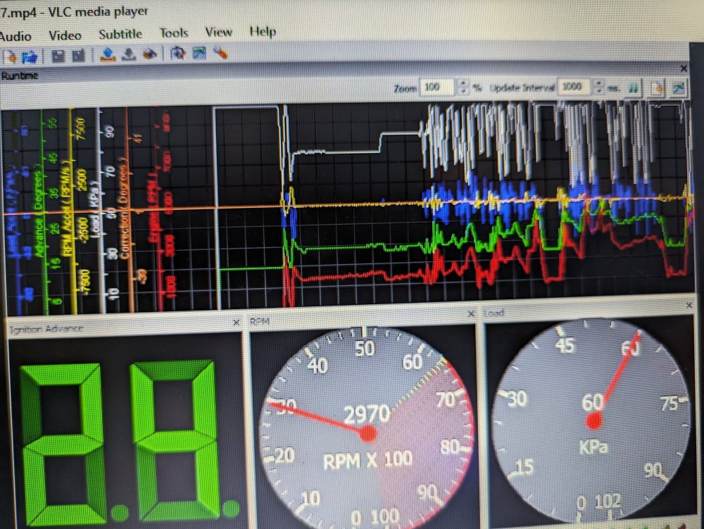
My burrent concern is the map sensor. It doesn't seem to get below about 50kPa and the signal seems very odd. The attached grab shows some fairly lengthy periods of full throttle which seem to be spiky, rather than consistant, and I can hear some of these periods of accelleration when the dial is showing 100kPa. I can't see that there's a way of calibrating the MAP sensor, so I'm getting suspicious that its a dodgy map sensor.
Before I get too carried away I'm going to install the plenum Toby gave me, check the soldering on the board, and look into the cost of a new map sensor.
Any thoughts from sideways on things I've missed or overlooked? I'm trying not to be biased, but I have a suspicious mind to the thing being broken which is probably clouding my judgement...
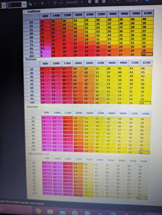
I've included a screen grab of the drive recording, and a photo of all the spitfire related maps I've found, including the one I'm running at the bottom, called generated map. I think the matt and rob maps are both generated by forum members here!
-
Sadly a little far from this part of the country for me to drop by (evening cub camp commitments with my eldest). Good luck, and fingers crossed it's running better than ever!
-
Cam timing is now sorted. Rear carb bowl decided not to fill, but now also sorted.
Ongoing are: Possible airlock after refilling the cooling system. Dodgy power to the megajolt, via the inline fuse holder I put in. Ignition barrel still not sorted.
However, it now drives the best I've ever had it. It does still feels a bit sluggish at higher rpms, I think it should feel more eager to meet 6k rpm, but that should come out in the wash at the rolling road.
Hopefully I'll get a good few drives in before then to flush a good amount of fuel through the system and get the carbs happier.
-
1
-
-
I'm going to assume that bad obsession Motorsport, and the fanatik gt6 build channels are mostly known about, but having just watched an interesting video, I thought it might be of interest to share other YouTube channels in case the algorithm isn't sharing with you what it shares with me.
Superfastmat is a man currently making a bike powered saltflat racer. He has various other impressive projects in his back catalog and uses lots of interesting and fairly accessible DIY techniques.
-
I just type @ and then start typing the username, then you click on the suggestion. That works for me @JohnD
-
Thanks for the suggestions. A spirit level did cross my mind, but couldn't work out a way to "zero" it given the car was on the wonk slightly. I didn't realise taht such items existed relatively readily availably.
@Escadrille Ecosse lining it all up like figure 61 is the bit that started all my doubt here. When I do this as best I can (engine in, bonnet on), it appears that it won't get close to this at all. One tooth either way leaves the crankshaft some way away from the indicated TDC.
Maybe my engine and pulley arrangement are similar to this: http://mgf.ultimatemg.com/Triumph_Spitfire/Cam_timing/index.htm but that example seems a fairly extreme amount out.
Hopefully I'll have a piston stop made by this weekend so I at least have TDC known to a reasonable accuracy. Then hopefully feeler gauges/ rocker rattle method will give me camshaft position accurately enough that I can get it started again. At which point I might take up @mpbarrett offer of the timing light to set the meagjolt advance. Then I think it just needs an oil change and some miles to make sure anything that's going to rattle loose does it before the rolling road!
-
The new timing chain is on, but I'm now questioning the cam timing. Careful measuring meant I put it back together previously as it came apart from when I got the engine, but I'm now questioning the accuracy. So I'm printing out a degree wheel today and going to try and find the bits to make a sparkplug piston stop. THis should allow me to do a slight modification to the ELOO method that @JohnD has written up nicely in the archives here.
My question for those that know is this: If I measure the point where the rocker arms become unloaded for inlet and exhaust and bisect that to get the mid point, is this the equal lift on overlap point? This would be significantly simpler for me to do, mainly becuase I don't have two dial gagues.
My current thoughts are that this is right, and sufficiently accurate. It will also greatly simplify and speed up the job, and while it may be pushing towards the bodge end of the engineering spectrum (as opposed to the science end), it should be within the realms of the 1/4 tooth (2.17°) accuracy and therefore not a big limiting factor.
Any thoughts or considerations? I'm under a bit of a strange time pressure on getting it back running. I have plenty to think and plan, but very little to actually do any hands on work!
-
A new barrel and chain kit are on order. I think I might try and get the chain cover (and tensioner) from the 1500 on the 1300. It's got a graduated pointer on the front, so I should be able to measure static timing with my dumb timing light. Fingers crossed I can get it sorted this weekend, but the garage has been re-purposed as a temporary store room while spitfire was out and about, so there's sorting to do. That or I brave the elements. The weather gods look to be kindly at the moment, but with all the wind that can change very quickly!
-
Took a trip to the local tssc meet last night, and the guys were all very helpful. Confirmation that something is off with the fuelling, and the discovery that there is quite a rattle that's most probably the timing chain I re-used. I put a new tensioner on, despite the warnings here as the old one looked pretty worn. So I need to get the timing cover off and investigate.
Fuelling issue seems like it might be worn jets or needles. Need to have a look at that too.
Dyno clock is ticking...
-
1
-
-
The rolling road is booked for a months time. They are booking 6 weeks in advance, and came from a recommendation so I'm optimistic about the results. However the spitfire doesn't seem so excited as it refused to allow me to even put the key in. The ignition barrel all but gave up on me a week ago with the symptom of the key not going into the ignition. It's worn to a point that the no1 tumbler pin comes out too far and almost falls out, it wedges in the keyway so that the key won't go in. Took a while to work that one out! Eventually I managed to get a look at the correct angle and poke it back into it's pocket with a multimeter probe and then slip the key in.
So next job is to try and get a replacement ignition barrel and swap it out.
-
Perhaps this is an area where unless it's horribly wrong it's basically fine?
-
Just realised shimming is a compromised solution for when you skim the head and effectively increase the pushrod length to the point you run out of adjustment in the rockers.
-
@Escadrille Ecosse of course! The fixed point is the top of the movement, when the valve is closed, so you want to shorten the pedistal to drop the pivot point. More lift = more open, as you can't get more closed than closed!
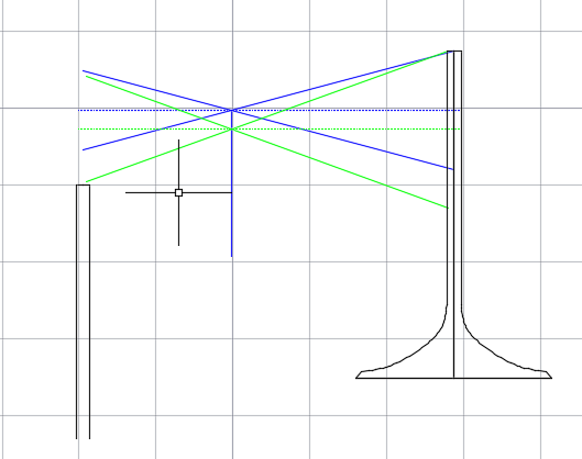
Edit to show a quick sketch I put together to helped me understand a little better. It shows the push rod on left, valve on right. Blue lines being a notional standard geometry, and green being a higher lift geometry. I have somewhat picked numbers out of thin air to allow my brain to see it, but I show 1.5: 1 rocker arms and probably a rather extreme example of about 30% lift increase for the green- the blue is 15° max rocker rotation away from the horizontal with the green being 20°.
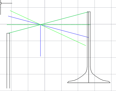
It shows how rocker pedista, and pushrods need to become shorter to accommodate higher lift and how all the geometry moves away from optimal as the angles increase. Trying to deliver this higher lift without moving the rocker pivot point would be even worse (second image).
-
2
-
 1
1
-
-
I'm thinking out loud here, so please correct me if I'm wrong (and don't be upset if I'm attempting to teach you to suck eggs)! I belive the goal is to have the rocker arm movement be symmetrical around horizontal*. I.e. fully open and fully closed valve are equal angles away from horizontal. This way you keep the angles as small as possible and minimise any unwanted horizontal forces. I think the order would be:
Measure pushrod (cam lobe) travel, and calculate/Measure valve stem movement based on rocker geometry.
Calculate 1/2 way point in valve movement cycle.
Shim the pedistals to make the rockers sit horizontal when the valve is at this half way point.
Set pushrod lengths based on this rocker arm geometry.
Check for binding
Check some more for binding!
*I'm not certain this is correct, it might be that with the valve closed the forces required to move the valve are lower than the forces to move it when fully open, so you might want to limit horizontal forces at fully open valve geometry. I assume the roller rockers will help on the valve stem end, but the pushrod geometry can be tricky too. I assume pushrods at too high an angle is a contributing factor to your issue.
-
It works! Megajolt behaving and it revs a lot more freely now. Fueling is not great now though. I think the carb jets and needles need a clean as I couldn't get the thing pulling right. Enough glimses of performance to get me excited about it when it's properly sorted, and enough for me to be happy to book it into the rolling road and even signed up to the Stilton Cheese run on the 21st April, which seems like a fairly relaxed run out and relatively local.
-
3
-
-
Given the drift on the few threads I've started with specific questions on my car I thought I should start a dedicated thread for what I'm doing on car.
Summary so far is:
Polybushes added almost everywhere. I've used a mix of red and blue to try and keep it from being too crashy.
Lowering springs from D Faulkner springs. 2.5 Inch ID 9 Inch Free Length 320Lbs spring rate
Lowering block at the back 1"
Braded brake lines.
Replica minilite alloys.
Electric fan with thermostat.
Re-built FD mk3 1300 engine, standard block.
Bigger valve head with a 9.5:1 and a bit of valve fettling. 1500 manifold with twin HS4 SU Carburettors.
Megajolt ignition.
Tubular SS exhaust manifold. Stainless exhaust into carbon motorbike backbox (a nostalgic relic from my CBR600FX)
Various usual brake overhauls, synthetic gearbox and diff oil, new trunion bushes, etc. etc. etc.
I've been chipping away at a few projects to get it running properly. Megajolt is hopefully almost ready. I ended up waiting for a replacement chip in the hope that I could swap out the fried one, but after a couple of false starts, I've given up on that, so I'm putting in the new(er) megajolt I bought from ebay. Only problem is that this was set up for TPS, so I've swapped the MAP sensor off the old megajolt onto the new one, and hopefully will get that re-programmed with a reasonable ignition map, and tell it to use the MAP sensor rather than TPS.
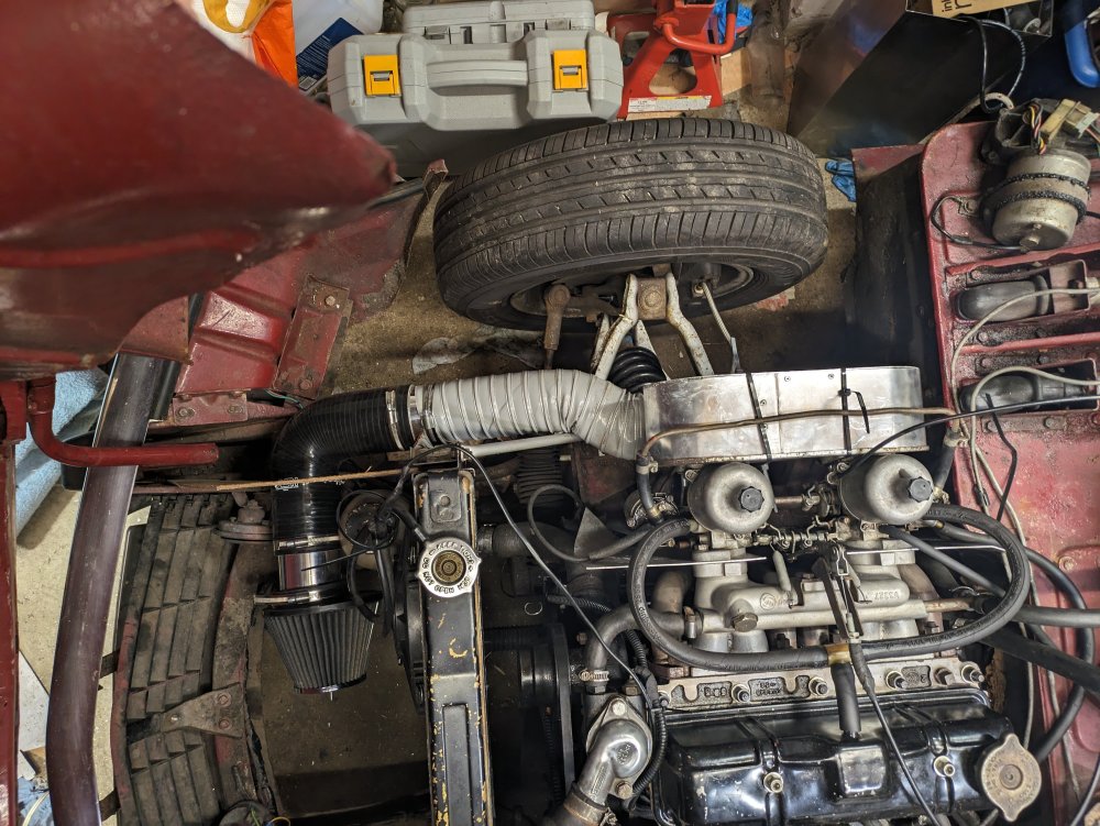
While this has been going on I've put together the air intake system, which I've been collecting parts for for years. Even so it's still a bit of a prototype as the plenum needs revisiting, and holding it in place with zip ties is not a permanent solution. I had a clamping failure when bonding the aluminium together. Somehow didn't manage to weigh it down evenly, so I think I will need to grind/file off the adhesive and re-apply. The gap is bodged at present, but tested watertight.
I will say that despite my clamping issue, MMA (methyl methacrylate) adhesive is rather good. No need to prep aluminium, goes on like silicone and cures to handling strenght in 12mins with working strength in 30min. So work fast and make sure you have spare mixing nozzles, but it's really good stuff!
So don't look too closely at the airbox, but the design principle is to maximise plenum volume in the availible space inside the wheelarch, then use large bore tube to connect to an oversized air intake filter in front of the rad.
Other advantages are that I'm not fiddling with multiple components and gaskets everytime I want to take the airbox off to check the carbs, and I have some 3-d printed low profile velocity stack to connect inside the airbox to smooth out the transition too. This is another future addition as they need a bit of fettling.
The goal now is to confirm the mejaolt works, then get it booked onto a rolling road to refine the ignition map and get the needle selection right.
I'm happy to hear any comments, or warnings, on the design or execution of the inlet manifold system. N.B. the plywood deflector in front of the radiator is a placeholder, and I'm aware that some of the fabrication is a bit ropey, but it should be good enough to get me out driving the thing!
-
2
-
-
13 hours ago, PaulAA said:

That is looking particularly beautiful!
-
1
-
-
I've that very same Victron unit in my van charging my leisure battery off a 100W panel. It seems like a good bit of kit, but I've not yet had the chance to properly test it. Hoping to get away over easter so will tax it a bit then.
-
We all know the longest lasting solution to any problem is the temporary fix which works!
-
2
-
-
I tend to use them for temperature comparison, rather than absolute temperatures. If you're looking at below about 100°C then using some black insulation tape to get a matt black finish is a good tip.
-
1
-


First Race of 2024 - CSCC Donington , March 23rd
in Events and Motorsports
Posted
@JohnD I think I should be able to attend Silverstone on the 22nd June, and would be more than happy to help out.