


oldtuckunder
-
Posts
1,643 -
Joined
-
Last visited
Content Type
Profiles
Forums
Blogs
Gallery
Events
Everything posted by oldtuckunder
-
Repeated #5 Big End Failure Triumph 6
oldtuckunder replied to oldtuckunder's topic in Engine and Ancillary talk
Marcus messaged me with a link to a thread on the CT forum with references to his work around the distributor drive bush which was confirmation that my problem is being tackled in a sensible way. Machined my bush today and easily removed 3mm from the diameter so have added a further 60 sqmm of flow area without the mods to the cavity yet to come. But anyway whilst reading the CT thread I came across a statement and pictures that were very relevant to another issue I was going to check when I get the crank back from balancing. "Bigg ends are ok though, and rods are tight fit too onto crank sides, 1.5 thou." Now whilst they were prodding around my block yesterday and generally discussing oiling problems on competition engines one of the questions raised were what clearances did I have on the Rod's. Now at first I assumed that they they were talking about bearing clearances so dived in with I was going to increase them to .0020, only to be told no "not those" (although agreed that for the size of journal .0020 was a reasonable choice) The clearances between the side of the rods and the crank flanges (which to be honest I hadn't thought to check) Anyway I was told in their experience you need at least .015 - .020 sideways float on the rods, and it was explained to me thus "by the time the oil has worked its way out between the journal and the BE shell "its nackered" you want to get it out and away as fast as possible, anything you do to restict the flow of oil out the bearing when its getting to the edge is just forcing oil to sit in the bearing and at 6K rpm plus its getting the absolute life kicked out of it and will quickly fail. It was strongly suggested that I check this clearance when I get the crank back, and if it was tight think about either relieving the cap sides of the rods, or notch each side of the rod cap with a 1/16" - 1/8" groove in a vertical direction i.e. pointing up the rod towards the Piston. They showed me a rod from (I think a Riley) they were rebuilding, which has some really expensive forged rods (but which still looked just like my cheap forged rods) with a neat groove cut in each side. As they said the objective is to get the worn out oil away, but pointing it vertically does incline it to go up to the piston crown and do a final bit of lubrication and cooling. I think in my trawlings a year ago I think I found mention of such a grove being standard (or maybe an optional extra) on the Carrillo Rods, but hadn't thought much about it. Anyway one more thing to check, and one more possible weak link in my lubrication chain. Alan -
Repeated #5 Big End Failure Triumph 6
oldtuckunder replied to oldtuckunder's topic in Engine and Ancillary talk
Well funny you should say that! I had an interesting field trip yesterday with my Block and Bushes. First I dropped off all the bottom end for balancing, and whilst there consultated the wise old heads, who said Hum thats a difficult job for someone to set up to do, but why don't you start with xxxxx ltd (who just happend to be the first people on my list anyway). Get to xxxxx ltd, and the old boys (well actually for engineering shops these days "young boys" as they are only in their 50's) get the block in on a bench measure it and the bushes, go measure a couple of machines and shake their heads and say can't do! Whereas in my innocence I had thought this was a job of bunging the right size drill and reamer down there, they explained that, no it had to be machined and getting the angle off by 1 degree might mean the oil pump/distributor shaft siezing. However why don't you take it to "Lawrence" if anyone can do it he can. So 20 mins later I'm at a small industrial estate in the middle of Worcestershire outside a unit with no name plate wondering if I'm in the right place. Inside its an Aladins Cave of old engines, gearboxes and who knows what, and by old I mean immaculate pieces of engineering from previous era, rather than a pile of oil covered junk. And two old boys (and thats saying something) and a huge workshop of old machinerey and also some that I recognised as the latest kit. Long story short, well about the same story about the difficulty of doing it, if I left it they would ponder on it, could probably do it at some time in the future, but if I wanted to get the engine back together this year or next year I might be pushing it!. Had a cup of coffee and beautifull tour of the workshop and got to see some amazing work going on on massive pre war cranks, blocks, gear sets etc, they certainly wern't trying to get rid of me. Anyway they finished by saying you ought to take this to "Jeremy" if anyone can solve the problem Jeremy can. So armed with a map drawn on the back of an envelope (no address no phone number) I set off further into the wild's and end up at some farm buildings in the middle of nowhere. The yard however was full of expensive looking car trailers and a collection of cars in various states dating from the 30's thru 60's. And inside the workshops a collection of eye watering machinery like Rolls Royce, Riley, Single seat ERA's and other exotic machinery in various stages of restoration, with a team of about 6 guys. Was introduced to Jeremy who came and looked at the block and the problem, and very quickly came to the same conclusion, what would have been a piece of piss in the factory with pre-set workstations would be a nightmare to do as a one off. But what's the problem? Spent at least half an hour looking at the block, the oil ways, asking about the prep of the rest of the engine, gave me at least half a dozen other things to check on the rebuild. He checked my cross section calculations, proded and measured inside the cavity, inspected the bushes, and concluded that if we machined a 2mm waist in the old bush (as the walls are good and thick) , and used some long carbide cutters to clean out the cavity we could easily get a cross section of around 200 sqmm. Not as big as the new waisted bush, but way way bigger than the cross section of the oil gallery itself. Also confirmed what Nick had suggested that the size of the oil holes drilled in the bush would make little or no difference as It was the clearance between the shaft and the bush that would control the flow. And actually noted that the shaft clearance in my old bush was tighter than in the new repro bush anyway! So was given the choice, I could sit there for an hour or so with their tools and do it myself, or he would get one of his "boys"! to do it over the next couple of days and I could pick it up when I was picking the bottom end up from balancing. Feeling guilty about the time I had already taken, and finding that a cash donation of a couple of brown notes would get the job done, I opted to leave it there, whilst I would turn the bush down on my old Myford as that was well within my capabilities. So whilst it took me half a day to get there as opposed to Flatter4's lightening conclusion, the result is the same, and I had a really interesting half day out, and learnt a lot! Was pondering last night over a glass of wine, what going to happen in the next decade when most of these people are no longer around (most are already well past retirement) , where will things get remade, repaired? Alan -
Yes we run a computer software company "for a living" so I know that I'm 99% secure (the odd one percent even gets the NSA) The symptoms are fairly typical of dns hyjacking, where some dns servers have been populated with fake entries, I think you can buy this service if you know who to talk to! Alan
-
If you do a google search for example "Triumph GT6 Sideways Technologies" and take any of the first results that google provides to what looks like pukka sideways topics, a lot of those links are highjacked to filestore321.com and adds for filmfanatic.com (and probably other nastier stuff). The interesting thing is the links aren't always broken, sometimes the same link will take you clean into sideways and sometimes off to filestore321, it kind of smacks that someone has frigged some dns entries somewhere. PS doesn't seen to matter what browser, see the same thing in I.E. and Chrome. Alan
-
Repeated #5 Big End Failure Triumph 6
oldtuckunder replied to oldtuckunder's topic in Engine and Ancillary talk
Ok bad news I think. I think I'm going to have to get the bush housing in the block machined to take the larger waisted bush. Getting the block out in daylight now I have it back, and prodding around down through the existing hole, I think my conclusion that they had a casting problem there might be born out. As far as I can tell the casting wall around the LH outside of the bush (i.e. the side where the pressure idiot light switch screws in) is severely compromised by material, maybe down to 50% or less, whereas the RH side where the drilling to #3 main exits is clear. However taking some measurements its clear that even if they were both clear the open area would still be less than the area of the drilled oil gallery. So my calculations are: Area of drilled oil gallery 12mm = 113 sqmm Existing non waisted bush area of passageway around bush 12mm (h) x 3mm (w) = 36 sqmm x 2 (each side) = 72 sqmm Waisted bush drilling 27mm waisted diameter 19mm gives as area 19mm (h) x 8mm (w) = 152 sqmm x 2 = 304 sqmm So if my casting area was good it would be 72 sqmm, but as one side is compromised by 50% I think I only have a cross section of about 54 sqmm way under the size of the main oil gallery drilling. Whereas the waisted bush approach guarantees a cross section of 304 sqmm around the bush. So I think I know why they changed. The interesting thing given my problem at #5 BE is that one would assume that that a restriction here (even though its where the feed to #3 main and #4 & #5 BE is) would actually cause more of a problem for the mains and BE's forward of the bush. But maybe that was the next problem that was going to hit me if #5 BE hadn't given up first. Alan -
Repeated #5 Big End Failure Triumph 6
oldtuckunder replied to oldtuckunder's topic in Engine and Ancillary talk
Not apart from the parts books (and of course my own engine) but the books are fairly explicit: Bush oil pump/distributor drive GT6 Mk1 Late Mk2 & Early Mk 31137978 Bush - Distributor Driveoil pump/distributor drive GT6 Mk3 Late 1149776 Bush oil pump/distributor driveVitesse Mk1 2 Litre 1137978 Bush - Distributor Driveoil pump/distributor driveVitesse Mk2 2 Litre 1149776 Bush - Distributor Driveoil pump drive TR5 1149776 Bush oil pump drive TR250 1137978 My engine is what I describe as a MK 1.5 2Ltr i.e. Its the MK1 head with the smaller head studs, but has the larger journal crank like the MK2's. I think all MK1 2ltr Vitesses from HC4501 had this engine, like wise the MK1 GT6 from KC5001. On the oil feed hole size, the only reason I can think that they changed it was either they had problems so reduced it, or found out they didn't need it. It would appear that on my engine the tolerance between the shaft and the old bush must be faairly good as I can decern no difference between it and the shaft in the new bush. The only thing that makes me suspicious about the hole size is that the shaft is machined with a groove and a screw thread so it is in effect acting like a small oil pump so it is just the tolerance that controls how much oil is lost via that route. Of course don't forget I'm looking for culprits so anything to me looks suspicious at the moment Alan -
Repeated #5 Big End Failure Triumph 6
oldtuckunder replied to oldtuckunder's topic in Engine and Ancillary talk
Ok here's a shot of the two bushes together, radically different, but I'm not sure why apart from the oil hole size. The oil hole(s) on the later waisted bush are about 1/6th - 1/8th the area of the earlier bush so I think inclined to waste less oil at this pinch point in the gallery. What I don't understand is why apart from making the hole smaller why they bothered with the change. The shaft diameter where it goes through the gallery is almost the same 19mm on the waisted one and 20mm on the earlier one, but not enough to make any significant difference, but the size of the press fit part of the bush has gone up from 20mm to 27mm, apart from having to machine more out of the block, and making the bush more complex to manufacture, what did it achieve? I wondered if if made the oil gallery bigger through where the distributor bush is, but looking at mine there is a nice cavity around the bush anyway and drilling through at 27mm wouldn't make it any bigger. The only thing I wondered was if they were getting casting problems in that area i.e. to get the chamber around the bush they must have had to have a plug of sand there, and maybe they had quality problems and sometimes the chamber wasn't formed properly, so wacking a biiger drill through solved it with a waisted bush. But if that was the problem its interesting that whilst they swopped to it in the MK2 Vitesse and all the other 6's they carried on using the old bush in the GT6 right into the early MK3's. Anyway just trying to decide what to do, I wan't smaller holes as thats an obvious potential oil loss, but I don't want to try drilling the block out to take the waisted bush. So I think I have to have a go at turning the waisted bush down to the right diameter, just worried that if I don't get that interference fit just right I'll either damaged the block pressing it in, or if too loose end up with the bush spinning in the block. I haven't tried machining anything that precise in the old myford, but I guess it has to be worth a try. Alan PS. Block and crank back from surgery, block main bearing alignment was about spot on but they said as they were all set up they just cleaned it up by a thou just to have perfect bearing seating surfaces. Crank was out of line by about .007 on #2 and #3 main journals which Rob said was almost certainly an effect of #5 BE getting hot and the crank undergoing a stress relief (said they see a lot of it in the 6cyl BMW cranks) Any way corrected and reground, MB and BE both coming out at .020 under so hopefully lots of meat left. Off for balancing on Monday. New forged rods arrived, in the end due to doubts about weights trying to match one new one with 5 older ones, they did me a really nice deal on a complete new set which all came in under 1g of each other acording to my scales, but 12g lighter than my originals (so at least I don't have to grind away at 5 rods to bring them down). So out of the original good 5 (which have only done a few hundred miles) I can keep one as a spare just in case, and will have a set of 4 to sell to someone with a Spit or MG 1500 whch uses the same rods.
-
Baffled Sumps, Angled Oilpumps And Oilsurge
oldtuckunder replied to Nick B.'s topic in Engine and Ancillary talk
Thanks for the feedback, usefull. I think the accusump should be almost instantanious as if the pressure in it is greater than that in the gallery it will instantly feed. On the engine/oil temp I don't know but I suspect that the oil is below optimum temp for a fair while after the engine coolant has reached it's, don't know but fitting the oil temp guage will let me know. As to if I need an accusump type of device if the sump is baffled well, I don't know but I'm in sort of belt and braces mode at the moment. To be honest I'd fit the Octopus/Spider thing I built as well but I have convinced my self that I think that is over kill, but I am going to keep the extra oil pressure switch in #1 port of the gallery to keep an eye on it. Interesting all the pictures on this forum of Vitesse & GT6 sumps all show open rear chambers, both my original and the spare I have just bought have an original works flange and mesh filter where you are all fitting your top baffle plates, well not sure of the height yet, but it gives me something to mount off. Alan -
Hi John You might like to add one of these to the rig Digital Engine Tach Tachometer Hour Meter Gauge Inductive for Racing Motorcycle ( 181296233782 ) £9 I just got one as I wanted to check what a couple of installed electronic taco's were telling me, seems to work well out of the box. Alan
-
Baffled Sumps, Angled Oilpumps And Oilsurge
oldtuckunder replied to Nick B.'s topic in Engine and Ancillary talk
Sorry for resurecting a long dead thread but as it was on the same topic it seemed to make more sense than starting a new one. Been working on designs for flap baffling the sump and windage trays (stealing many previous inputs on this forum) and I've arrived at a conundrum that I would appreciate thoughts on. As well as baffling the sump I intend to fit an accusump type device, I'm going to use the port between the oil filter and gallery, and my intention is that as well as using it as an accumulator so that I can do a pre oil before starting, certainly in competition I will run it in open mode so that if the pressure in the system drops it will auto feed from the accumulator. I think the accumulator I have decided to go for will hold around 1ltr oil, which I think should be long enough to cope with any surge loss (if the baffling isn't as good as I think it will be). I'm not planning on fitting the oil cooler initially as in sprints and hill climbs I think a bigger problem is actually getting the oil up to temperature, but I am fitting the oil temp sender and guage (that I didn't have time to last year) I think I'm going to fit the sender in the drilling direfctly above the prv as that should tell me the temp of the oil being pumped out of the sump. If I see that the oil temp is getting high then I will just fit the cooler on a thermostat ( I already have the plumbing on the filter so its a quick fix if I start seeing higher than I would like temps) So the question is if I baffle the sump well, and use the accumulator do I also need to enlarge (deepen) the sump for even more capacity? Alan -
That takes me back 30 years
-
You may think that I can't possibly say
-
The year before last when I was using standard rods, I bought some very nice bolts from Mark at Jigsaw for around £3.50 each I think they source them in Germany. I know Jigsaw won't use ARP's in their race engines after a few spectacular failures.
-
Repeated #5 Big End Failure Triumph 6
oldtuckunder replied to oldtuckunder's topic in Engine and Ancillary talk
That is the steel backing that you are looking at! -
Repeated #5 Big End Failure Triumph 6
oldtuckunder replied to oldtuckunder's topic in Engine and Ancillary talk
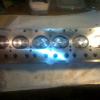
Hi OK I think I have a clear enough small enough image to post. As I said earlier the bearing in #5BE span like a good un in the rod and got squeezed out and folded over the end of the cap, and I remarked that one of the tangs was broken but still wedged in the groove in the cap. I assumed that this was all damage caused by the bearing seizing on the journal and then just ripping the tangs off as the shells found it easier to rotate in the rod than around the journal! So I was stripping #2 Rod (zero sign of damage or wear) to weigh it and by chance as I removed the shells I took a good look at the tang on one of them, see picture below. I'm fairly certain that I can see two small hairline cracks emerging (carrying on) from where the end of the real crack created in making the tang ends. Any thoughts? Alan
-
Repeated #5 Big End Failure Triumph 6
oldtuckunder replied to oldtuckunder's topic in Engine and Ancillary talk
That's OK I'm getting used to those -
Repeated #5 Big End Failure Triumph 6
oldtuckunder replied to oldtuckunder's topic in Engine and Ancillary talk
Thanks guys I think I'm heading in the same direction as to cause plus I think the MK1 Distributor Bush may also not be helping. Spare sump pan arrived to day so will be starting design work on it, to enlarge, baffle etc. As it will be deeper than the original I have to extend the oil pickup and have seen pictures of those Chevy Pick ups and has been pondering designs in that area. I'm hoping with this, good clearances and a type of live Acusump that I may get on top of it. On the bearing material issue I'm about to try and take a picture of one of the good BE bearing shells for comment, as I really don't like the tangs. Not sure if I can get a good enough picture of the tiny detail but will try. Alan -
Repeated #5 Big End Failure Triumph 6
oldtuckunder replied to oldtuckunder's topic in Engine and Ancillary talk
sorry some delay on the post it should have this attached: An interesting point on the oil feeds anyone noticed that the feed holes on the main bearing journal to say 4 & 5 BE are only 120deg apart, i.e there is an unequal timing between the oil feeds to the BE passing over the oil feed to the Main journal. Un fortunately having put the scrap crank back in store and the hopefully good one is being reground i'm not sure if its #4 thats passes the oil feed and then #5 120 later and then #4 240 later or vice versa. Its probably a dumb thought but who knows if it could make a difference. On oil it probably says that the recommendation I had to use 5W50 was close to the mark. Alan -
Repeated #5 Big End Failure Triumph 6
oldtuckunder replied to oldtuckunder's topic in Engine and Ancillary talk
-
Glad you got there, one of those problems that come along where doing the trivial bit seems to take longer than the original task. NB. For running it indoors and quieter, I have an 8ft length of flexible air conditioning ducting, its an outer foil tube with someting like a rockwool lining sandwiched between another foil tube. It scruches up to about a 1/5th of its length for storage. Its the stuff they use in roofing ducts for noise attenuation and also they can waggle it through awkward spaces. Its about 10" OD with about 6" ID, I just bung it on the exhaust pipe and out the door, works fairly well and dirt cheap. Alan
-
Repeated #5 Big End Failure Triumph 6
oldtuckunder replied to oldtuckunder's topic in Engine and Ancillary talk
Thanks for the thought :-) And whilst I'm sure it wasn't bent as they were new forged rods at the last build, it may well be bent now, well its scrap anyway having reached some silly temperature. Alan Possibility of a bent con rod. Just a silly thought. -
Ok I may be stupid (correct that OK I'm stupid) But to try and simplify, If you disconnect the starter cable (at the starter end) and connect a positive jump lead to the starter it turn's Yes? If you reconnect the starter cable and apply a jump lead at the solenoid end of that cable, it fires? if Yes move on, if No you have a faulty cable, it may be passing a small voltage reading current but won't hack any real amps. If Yes connect jump lead to battery terminal of solenoid. and then with another one jump to the starter terminal of the solenoid, does it turn? As this is really just connecting the battery directly to the starter if its a No then one of the jump leads is faulty! Disconect the jumper across the two solenoid terminals (which of course you have already done otherwise the starter woould be turning) Apply current to the solenoid trigger, does the starter turn? Yes? well I think you are working, No? Faulty solenoid don't care if there is still voltage at the starter terminal of the solenoid I think the solenoid is faulty. When you say the solenoids worked on the bench was that working as in when triggered the circuit was made between the batter and starter terminals, or working in that it would carry a heafty amp load? I think the two are different. Even dummer think about orientation of solenoid when testing, in one plane actuating the trigger may cause the solenoid to just be able to make internal contact across the terminals, but in another orientation it won't. I seem to vagually remember many (make that many many) moons ago when the Vitesse didn't want to start properly spending precious money on a new battery which didn't solve the problem, then concluding that the starter motor must be the problem and spending more money on a recon one, which also didn't solve the problem to finally change the solenoid which magically did solve the problem. The only upside is that I'm still using the same solenoid and starter motor some 30 years later! Alan
-
PS love the rig! Was wondering how to test a reworked sump pan before refitting the engine into the car. Parcel on its way to you
-
Is the engine block well earthed? A really dumb question but can you measure the current draw when you press the starter button, i.e. is the solenoid shorting to earth? I had one of the standard starter solenoids that had a cracked casing once, would work on the bench not on the car. My mind may be going but why would you want the solenoid to earth through its mounting? Alan
-
Repeated #5 Big End Failure Triumph 6
oldtuckunder replied to oldtuckunder's topic in Engine and Ancillary talk
Thanks Pete Your helping me formulate a plan, and in a way its good to hear that those oil pressure drops were too quick to spot by human eye as I was sure I had never seen my big red tell tale come on. So I think my plan of action is. Block and crank going off tomorrow Have Main Bearing alignment checked and corrected if necessary, Have the crank checked straightness and cracking See if #5 BE will clean up to something sensible, other wise get another crank (and get that checked) Get the oilways on the main journals countersunk to a larger size so that they all sit fully over the shell grooves, I cant see any downside to having them slightly bigger, and if I get the crank Nitrided it should ensure that the new edges of the countersunks aren't weak. I'll go for .002 bearing clearance on all the journals. Bearings I'll have debate with my self about (original VP2's are available for the Mains, Iv'e tried Kings and the new AEL VP2 copies on the BE's do I try something different like ACL Duraglides?) Replace the distributor drive bush with a waisted small hole one (I'm getting more and more suspicious about that bush remembering how much oil got pumped back up that bushing from the gallery when I was priming the system with an electric drill) Completely rework the sump making it deeper and much better baffling, extending the oil pick up (I don't like the standard one with the mesh bowl on I think it holds the pick up at the wrong angle and too far up). I had built a prototype Acusump type device and Octopus, however I think the Octopus bit would really only help the front part of the gallery (where I don't seem to have a problem), so I think I'm going for the Acusump device plummed in the large spare port between the Filter and the Gallery, using it as a pre oiler isn't going to do any harm after its been stood for a week or so between events, and if I leave it active when running hopefully it will take up any sudden pressure drop that may occur even after reworking the sump. Fit the oil temperature guage. I think that that's about all I can sensibly do, and then keep my fingers crossed for this season. PS. If anyone has a spare Vitesse/GT6 sump that they want to sell let me know, I think I'd rather have a spare in case something goes wrong with the extensive mods. Guess I could treasure hunt for one at Stoneleigh next weekend. Thanks for all your inputs, at least I now have a plan. I'll let you know how the block and crank check out in due course. Alan

