aoie
-
Posts
66 -
Joined
-
Last visited
Recent Profile Visitors
8,080 profile views


aoie's Achievements
Advanced Member (4/10)
-
Richard Sorry I never saw any replies to my post and missed your question! Have not tried putting the idle air into closed loop, working on my water and oil temperature monitoring before I re-visit the air control. IAC startup has been very stable however the plumbing from the IAC added about 100 RPM to my overall idle speed after warm up. Engine is consistently at 1000 RPM when running temperature is reached, this is up from 875-900 before I added in all the plumbing. On startup the IAC bumps the idle up to 1450-1500 and then backs back down to 1000 and is very stable at doing this. Its my hope that the throttle body air bleed screws will back the idle back down to 875-900 once I get back to it, I will let you know!!! Once I get the running idle back to 875-900 I will try the closed loop.
-
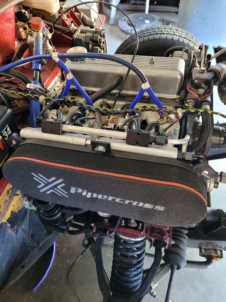
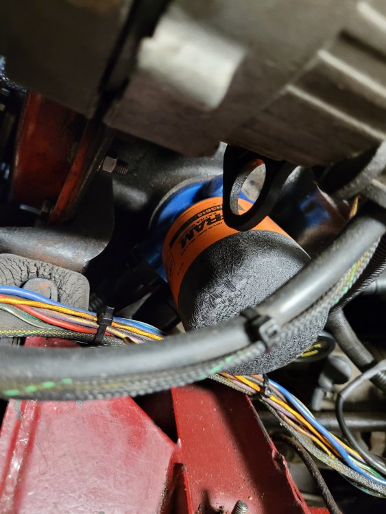
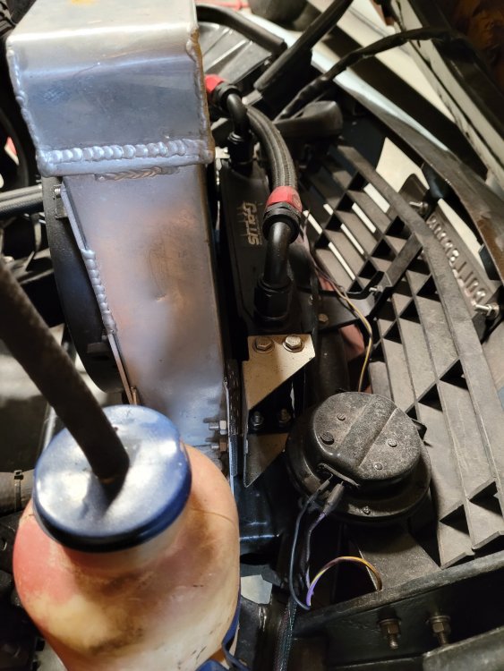
Thought I would start sharing some of my Spitfire upgrades starting with Idle air control modifications (with pictures). My EFI throttle bodies consist of 2 Borla 2900 series DCOE style with a standard/modified Pipercross PX600 air filter and back plate. I needed to shift the PX600 backplate to the right when I fitted it to the throttle bodies to clear the back fire wall, this gave unused room on the Right side near the water pump to mount a Ford PWM IAC to the backplate using the air cleaner plenum to supply IAC air. I'm running a microsquirt so my IAC options are limited to PWM types, and the Ford version is pretty inexpensive and easy to obtain. After mounting the IAC I did some fancy aluminum pipe bending with flare AN connectors to supply two off the shelf aluminum plenum air manifold blocks I mounted to the fuel rail. Inside the Air cleaner I just used standard copper plumbing. Throttle bodies came with only 1 set of air supply nipples pressed into back flange by manifold. I had been using them for my MAP sensor take-off until the IAC plumbing was completed. I then simply moved the MAP sensor takeoffs to bungs I had welded to the manifold. Throttle bodies also have air bypass control screws located upfront by the air plenum plate, but I decided to not use them and keep for small adjustments. Apparently my design was not to bad, first cold start bumped idle speed up to 1450 RPM before dropping back down to 850 after warmup. Let me know if you have any questions, happy to share! Andy


-
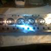
Thanks for the input! I did not think of the infrared thermometer tester that would put it over my three times needed rule before buying, and I can get one cheap. Always planned to monitor oil temp but no-longer have any inputs left on my Microsquirt. It would be easy for me to add in-line adapter at the cooler with a 3/8 port for temperature gauge at this time. Once I figure out how to add more inputs to the CAN-Bus inexpensively, I could then replace it with a sensor and add it to my DIY digital display on the Dash. I thought about a pressure gauge at the cooler but was unsure if it would give me false readings. My thought was even if the sandwich plate is blocking oil at low temps as it should, that It would not block actual pressure from registering in the cooler lines. Let me know if I'm over thinking this, if it could just act as an on off indicator that I monitor on the dash board for flow that's what I'm looking for at this time. I'm going to go ahead with the temperature gauge at the cooler idea since long term I want to eventually display and record it, will let you folks know what the results are. Picture of my DIY Digital Dash Gauge that can display CAN-Bus info form my MicroSquirt. Andy

-
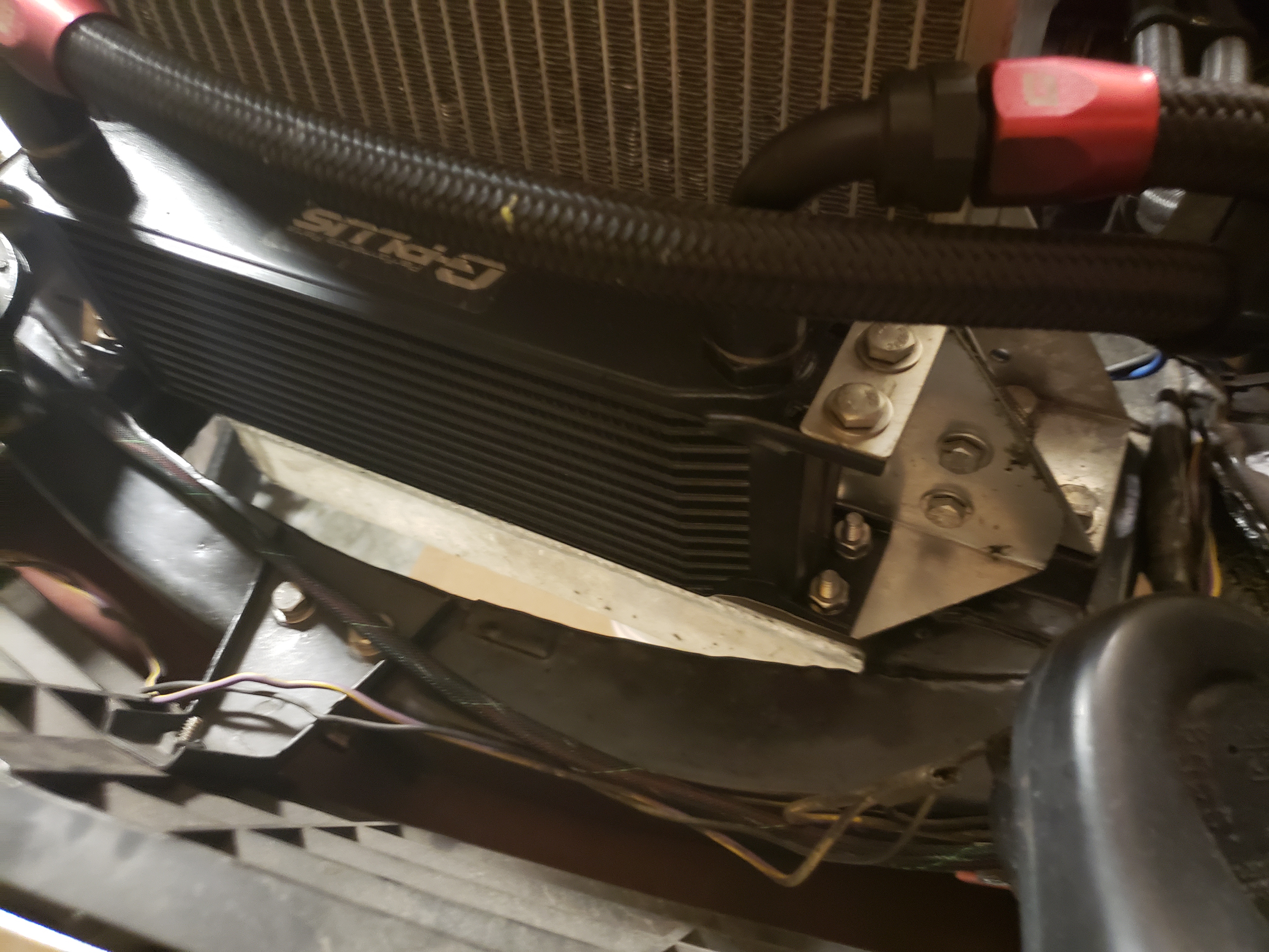
I believe I installed basically the same oil cooler several years ago, only difference is my cheap eBay purchase had AN connectors. I have had no issues but always wonder if the setup is working correctly (Sandwich plate with thermostat for flow)! Anyone have an idea what i could install that would indicate oil flowing into the cooler when it reaches the correct thermostat temp setting. My sandwich plate was also a cheap eBay purchase so you wonder about quality.


-
Just my opinion from the States! In NASCAR if Verstappen attempted to force the issue when someone had the inside track, the result would be the same every time! Fun to finally see real racing in F1. Andy
-
Thought I should share my Oil Cooler Pics! Buying a modern oil cooler using 10AN fittings was ridiculously cheap on eBay compared to staying with older UHF connections. Hard part was finding oil sandwich plate with 10AN fittings so I re-tapped one. You simply have no room around the spitfire oil filter to work with. Andy
-
Oh I was bad! Jigging Holes are on the block, not the head. Thanks for not jumping all over me on that mess-up! Andy
-
Plugged Jigging holes on my block with 1/2' brass rod I purchased off Ebay! One thing I did to help me shape the plug so I could have a nice press fit was to drill and tap my plug so I could press the plug back out with a screw down the middle. Andy
-
Picture of one of the blown gaskets showing small pin hole water damage caused by jigging hole.


-
Plugging the jigging holes on my head solved a chain of blown gaskets after I shaved head to produce around 9.0 compression ratio. Blew both a PAYEN and then a Lucas gasket, and could visibly see problems around the jigging holes when I replaced. Went back to cheap generic AK260 gasket from British parts Northwest in the States ($6.75 US), after plugging the jigging holes and have not had any issues since. Before I shaved the head, engine ran for over 10+ years on cheap generic gasket with no issues (Stock US Compression 7.5) !
-
I looked at up-rating my calipers several years back when I swapped my Spitfire front suspension for bigger salvaged GT6 parts I found on e-bay. Decided to just rebuild the 16’s that came with my salvaged GT6 parts for the experience. Rebuilding the calipers gave me the option to up-rate the pistons to stainless that you will not get with most purchased rebuilds. The calipers I rebuilt were in bad shape and the rebuild was awful, your brake caliper looks far worse!!!! Problem I saw with the Wilwood kits available for GT6 years ago was they used the Powerlite caliper that does not have dust-seals on the pistons. Does not look like anything has changed in kit offerings years later even though Wilwood has come out with several m16 models like the Dynalite that have dust-seals. Would probably have tried the Dynalite but the model was not available in the USA for several years . Interested if anyone has actually used the Powerlite calipers, and if they do need more than regular cleaning/lubricating with no dust-seals
-
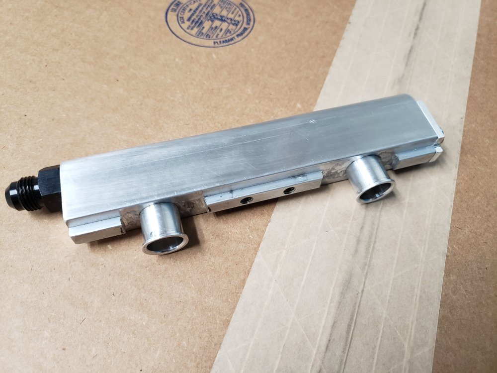
I have yet to actually use but found a latest generation BOSCH EV14ES injector 0280158284 with specs 12 ohm, 15.4 lbs/min, 161.9 cc/min, USCAR plug. Also found another with same specs with JETRONIC plug (0280158254). I modified my fuel rail using inexpensive aluminum extenders I found on ebay to adapt the newer style shorter injectors. rail

-
 Trying to fit EV14 style injector into recently purchased Borla DCOE throttle body that appears it be designed around EV1 style injectors! EV14 long injectors are a few millimeters too short, so I'm looking for EV14 standard size in the 150-200 cc/min range with USCAR wiring port that I can put a 14mm top extender bung that will be welded into the fuel rail. Does anyone have a decent reference chart or website on the newer 280158*** style injectors? I can find several sites with decent references on EV1 and EV6 injectors but not EV14. Two injectors model numbers I have found so far are 280158017 and 280158022 that have older Jetronic plugs, but have a 154 cc/min fuel rate in the range I'm looking for, and a decent $20-$25 USA dollar cost. Spitfire 2960cc motor.
 -
Since this thread is recent I thought I would just add on with recent question on Wideband systems! As stated previously I was using a PLX O2 Wide band system but was unhappy with system stability. Just completed wiring Innovate LC-2 controller (with gauge) and find the gauge reading is not matching output to micro-squirt, It's a full point off on AFR (i.e 14.5 on innovate gauge is 15.5 in tuner studio on the micro-squirt). LC-2 default settings are 1-5 volt wide band on output 1, and narrow band on output 2. At start of project I re-programmed output 2 for same settings as output 1, I then programmed in matching values in Tuner studio and downloaded to micro-squirt. After seeing the difference between systems I then switched/flipped the output wiring and the result was the same, so both outputs are putting out the same signal. My old PLX O2 system when working, the gauge reading exactly matched tuner studio micro-squirt display with no difference. Wondering if the folks using Innovate have seen the same problem or have had no issues.. Andy
-
Chris's Mkiv Basket Case restored to glory
aoie replied to Nick Jones's topic in Members Cars and Project threads
Nick I posted some forum pictures last year showing the lack of space between the Spitfire front pulley and steering rack! I had to take my trigger wheel setup back to the machinist a couple of times to fit trigger wheel more forward onto the pulley. Have you tried checking the clearance? Mine was close, but found out on first street bump (loud grind noise) that I needed much bigger gap! It looks like you did machine off some of the pulley backside, but I'm not sure! Andy