


Chris W
-
Posts
193 -
Joined
-
Last visited
Chris W's Achievements
Just passed my test! (5/10)
-
I haven't been here for a while but 'Thruxton Crash' popped up in my Youtube feed and the thumbnail featured a familiar looking Vitesse. Thought I'd better check that no John was harmed in the making of this film. Glad to see you are ok John, I'm sure the damage will buff out. Cheers Chris
-
It's a couple of years since I did GDPR training but I suspect this 'data harvest' would fall foul of the law and you can bet someone will crowdfund a test case now the 'cat is out of the bag'. The way I look at it is, organisations can only hold data for which there is an obvious and ongoing need. Patient records are only created and maintained with the specific purpose of providing care efficiently to that individual. The Patient's data cannot be used for any other purpose, regardless of the reason, good or bad.
-
Ha, the car has been off the road for so long now, I can't really remember but I don't think so, or I would have investigated it at the time. My understanding of the purpose of building in caster is to get the steering to tend towards the straight ahead 'hands off' but I may be wrong and I don't recall the steering not doing that. In reality, as Hamish implies, there are enough imperfections in an old chassis, it's probably just one of many things that could hamper optimal performance, even ignoring the 16 Stone nut behind the wheel The main 'oh bollocks' issue is just that having managed to get some time to start the reassembly, I've now got to wait for the new part. At least they are still available and in stock. Cheers Chris
-
This evening, I discovered that when rebuilding the front suspension of my TR6, having one trunnion with 3 degree caster (correct) and one with 0 degree caster (incorrect) is not an ideal set up! Just goes to show that when I removed the parts 3 years ago I didn't notice that on the near side, the upper wishbones must have been reversed too, else it wouldn't have been attached.
-
Dial Gauge Question
Chris W replied to Chris W's topic in General Engineering / Workshop Discussions
Hi Roger, I know what you mean. As the opening lines of a new Joe Walsh record put it.... Welcome to Cyberspace I'm in a fog The whole world's Digital I'm still Analogue -
Dial Gauge Question
Chris W replied to Chris W's topic in General Engineering / Workshop Discussions
Hi John, More lucky than you can imagine as Ted's relatives (quite rightly) had first pick of his tools and there was very little left by the time I was invited to sift through what was left. I can only assume they didn't know what it was. regarding zeroing the scale, I had figured it should be adjustable due to the knurling but it was pretty stuck and I didn't want to force it. Armed with your comment, I had another go and hey presto, it is now free to turn so thanks for that. There is was another gauge in the box with the name 'Mercer' on it. From 'feel' alone I would say it is better quality than the Baty gauge but I'll take your word for it. Maybe Rolls Royce and Bentley. The Mercer gauge is intact but the bezzle fouls the needle and there is no cradle or bracket to attach it to a stand. As far as use is concerned, yes I had in mind crank end float as the 1st and most obvious job for it but I guess there are a number of other applications. for crank end float I've only measured once and suspect the stability of my mounting but it is looking like movement is 8thou. -
Dial Gauge Question
Chris W replied to Chris W's topic in General Engineering / Workshop Discussions
Hi Phil, Thanks for the gentle way you pointed out my schoolboy error with decimal points!! Relating to my day job, a penny is 100th of a pound £0.01 so obvs 1000th must be 0.001 The good news is, as you say, the scale is a lot easier to read -
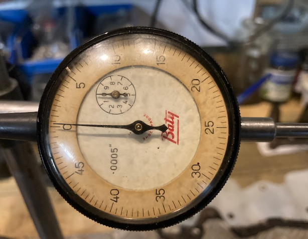
I recently inherited a Baty dial gauge and magnetic stand from a neighbour who was moving into a care home and needed to clear his workshop. Unfortunately there are no instructions and I wanted to see if any of the more experienced 'engineering' members could assist me with understanding how to read the scale. The 360 degrees of the 'clock face' is marked in intervals of 5 from 0 to 45 (50 being back at the 0 position) and there is a subsidiary dial counting full rotations. The dial face is marked 0.0005" which I take to be the scale. On this basis, I assume each hash mark represents 5thou so if the needle is pointing to 5 this means the plunger has moved 5 x 0.0005 or 25thou. Does this make sense and is my logic sound? As ever, all comments gratefully received. Oh, it turns out I can add a picture!!!
-
The rebuild that goes one step foward two back!
Chris W replied to michaeljf's topic in Triumph TR Series
Thanks Nick, Useful info. The nose of my crank protrudes no more than 10mm. Let's make this the last post on this subject, I'm a bit embarrassed about hijacking Michael's thread! Cheers Chris -
Another Trigger Wheel Question
Chris W replied to Chris W's topic in Ignition, ECU and Fuel Injection
Hi Ian, Thanks, I had no idea replacement crank pullies were still available outside the hugely expensive (and worryingly named) 'rattler' pullies. -
Another Trigger Wheel Question
Chris W replied to Chris W's topic in Ignition, ECU and Fuel Injection
Hi John, Sorry, my comment about the outer ring keeping up was more related to ignition timing (using a ring mounted trigger wheel) if the bonding rubber was marginal through age. The bit I was more interested in your view, was about the effect of removing mass from the ring and you answered that, thank you. Nick makes a good point that most of the mass removed would be replaced by the trigger wheel (assuming they are similar metals). -
Another Trigger Wheel Question
Chris W replied to Chris W's topic in Ignition, ECU and Fuel Injection
Thanks to all who responded. The depth of knowledge and experience never ceases to amaze. Nick's answer kind of confirms my gut feel that the teeth should be proud although Ian's arrangement suggests it isn't critical in the real world. In fact Ian's picture comes up on a Google search and was what I was referring to when mentioned 'neatest solution'. Triggerwheels website has wheels at 6.5" but the next size up is 7.25" which I feel might be too much or give clearance issues. There is a guy on ebay who I will probably use, as he sells the standard 165mm OD but also states that he does bespoke sizes. So Ian, your second picture shows a gap between the trigger ring and the meat of the pulley. I wonder if that is why you can get away with the teeth being flush. Also, your pulley looks new with moulding tags on the rubber. It is certainly different to my pulley. Is this an aftermarket pulley or an OE pulley from a different car? John thanks for your contribution, as I'm acutely aware that the rubber bonding on original pullies can be marginal and as Nick mentioned the proposed solution does rely on the outer keeping up with the solid inner! I'd also be interested (from the work you did on this) whether you feel that machining out say, 25% of the mass of the pulley would change its vibration damping characteristics, or more to the point, render them ineffective? Thanks & regards Chris -
Actually more than one and sorry if they have been asked before but I did look back through the history and couldn't find an answer. I want, eventually to move to efi so I have been collecting the necessary hardware. I need to mount a trigger wheel and the neatest solution I have seen is to machine the rear face of the pulley so that the trigger wheel sits flush with the remaining rear face. (CP TR6 engine). Q1. The pulley assembly is about 6.5 inches or 165mm in diameter. The trigger wheels I have looked at are also the same OD so the top of the 'teeth' would not be proud of the pulley but about level. Is this a problem or do the teeth need to protrude to be effective? Q2. If the teeth don't need to protrude, would it be advisable or necessary to machine a step so that there is say a couple of mm gap between the trigger wheel and the pulley? As I said above, I'm just collecting hardware at the moment so I don't have any installation instructions. Q3. My guess is that the longer notch/missing tooth on the trigger wheel is there to tell the system where TDC is? If so, the notch presumably should be in the vicinity of the sensor when the engine is at TDC? How critical is this, should it be in line with the start, middle or end of the notch? Sorry if these are numpty questions but any advice, gratefully received. Cheers Chris
-
The rebuild that goes one step foward two back!
Chris W replied to michaeljf's topic in Triumph TR Series
OK, thanks for the comments. You both are likely to have more experience of this than me........which is why I asked -
The rebuild that goes one step foward two back!
Chris W replied to michaeljf's topic in Triumph TR Series
Hi Michael, thanks for posting. Your spacer looks like it's machined steel, rather than cast iron so I suspect it isn't Stanpart. By the way, your rocker assembly looks very smart. Shame to have to cover it up!!! Cheers Chris